


TRIFECTA Performance
-
Posts
1,801 -
Joined
Content Type
Profiles
News
Store
Downloads
Everything posted by TRIFECTA Performance
-
 We certainly do!
 -
-
TRIFECTA: Big Turbo (EFR7670) + 2.0L LTG = 500WHP
TRIFECTA Performance commented on TRIFECTA Performance's article in News
Unfortunately not. The turbo in the article is specifically meant to bolt up to the 2.0T (RPO: LTG) in the Cadillac ATS and Chevrolet Camaro. -
TRIFECTA: Big Turbo (EFR7670) + 2.0L LTG = 500WHP
TRIFECTA Performance commented on TRIFECTA Performance's article in News
It can, but if it couldn't, we would ensure we did not exceed the limitations of the hardware. 👍 -
Hi all, This was ultimately a proof of concept that never got off the ground as a product despite our efforts to make it a reality. If there were a kit of similar design produced by another manufacturer, though, we would be able to tune it provided the engine were built up and sufficient cooling were integrated into a kit.
-
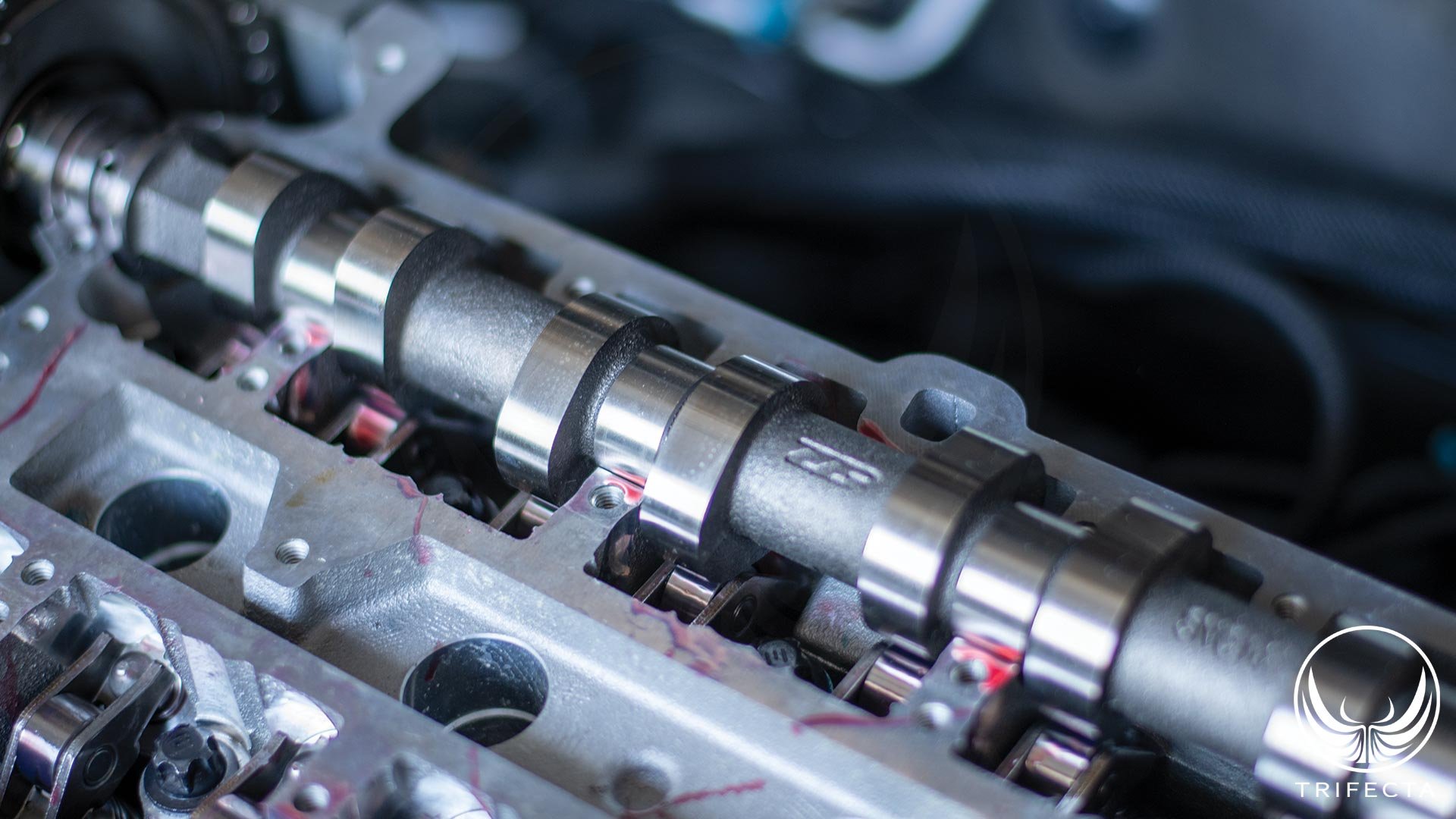 Figure 1 - ZZP Stage 1 intake cam Background on “cam” modifications Four cycle internal combustion engines (like the LUJ / LUV) follow a surprisingly simple concept. They are essentially a large air pump. The pistons descending the cylinder create a low-pressure area in the cylinder in which a mixture of air and fuel is drawn into. The mixture is compressed, and then ignited by the spark plug, sending the piston down the cylinder, generating horsepower. The cycle ends with the piston traveling back up the cylinder and pushing the exhaust products out of the engine in preparation for the intake of a new air / fuel charge. The camshafts are an important tuning element of these kinds of engines. The camshaft design controls at what point the valve opens, how much it opens (this is lift), and when it closes (indirectly controlling the duration for which it is open). A camshaft rotates at half the speed of the crankshaft, so one rotation of the camshaft represents the entire 4 cycles of the engine (two rotations of the crankshaft). When people talk about camshaft modifications, the most common terms you hear are lift and duration. However, there are other aspects as well, such as valve event timing – e.g., WHEN the valve opens, and closes in relation to top dead center (TDC). Overlap is an important tuning characteristic as well – this is the amount of time that BOTH the exhaust valve is still open (at the end of the exhaust stroke), and the intake valve is open (at the beginning of the intake stroke). Camshaft basics, and configurations The camshaft generally starts off as a forged metal shaft, which is machined to have lobes which transmit the lifting motion to the valve through a variety of different designs. The earliest “cam in block” designs, (which most GM V8 engines continue to use to this day) utilized lifters which ride on the cam lobe. These lifters would transit lift to the pushrod, which extended up into the valvetrain area, pushing a rocker arm up, which in turn would push the valve open. This is the OHV, or overhead valve configuration. Eventually engine designers realized there are certain benefits to moving the camshafts from the engine block, up to the cylinder head. Here, the camshaft – or camshafts (more on this in a moment) are in the cylinder head itself as opposed to the cylinder block. There are far fewer moving parts, since the camshaft lifters can directly activate a rocker arm, or in even newer designs, the follower is essentially a rocker arm that rides directly on the camshaft, eliminating the need for lifters. This is the OHC, or overhead camshaft configuration. Later, engine designers recognized the benefit of being able to dynamically adjust the timing of the camshaft related to the crankshaft while the engine is running. This is because what generally helps an engine make good low RPM power (torque) is detrimental at higher RPM (horsepower). When an engine is at lower RPM, you typically want the intake and exhaust valve events to happen closer to top dead center (TDC), and as the RPM rises, you typically want the events to happen later. The earliest camshaft phasing designs were able to adjust the camshaft timing on the fly to extend and optimize the power band, which was particularly useful on small displacement engines. Figure 2 - DOHC configuration As time went on, and technology improved, engine designs eventually incorporated two separate camshafts – one for the intake valves, and one for the exhaust valves – and independent phasing capability on each camshaft. Here, not only can the timing of the intake and exhaust valve event be adjusted on the fly, but also in relation to each other. Put another way, independent phasing authority on the intake cam and the exhaust cam allows valve overlap to be adjusted as well. This is the DOHC, or dual overhead camshaft configuration. There have been even more technology improvements, such as variable lift technology, which is used on the newest GM 2.0L turbo engine (the LSY), but these technologies don’t exist on the LUJ / LUV, so we won’t discuss them here. Making more power with cam upgrades Generally speaking, when someone says they have “bigger cam(s)”, what they mean is they’ve replaced the original camshaft(s) with camshaft(s) that offer higher lift and more duration. That’s precisely what the ZZP Stage 1 cam kit does for the LUJ / LUV. Why does this improve power? Higher lift means the valve opens further. By opening further, air /fuel mixture can flow into the cylinder more easily, just as the exhaust can flow out more easily. A valve that opens further presents less of a restriction. Longer duration means there’s more time for the air / fuel mixture to enter the cylinder and exhaust to exit. The ZZP Stage 1 cam kit increases both lift and duration on both the intake and exhaust side, but how they did it was quite innovative. The ZZP Stage 1 cam upgrade kit for the LUJ / LUV At the time of writing, for $349.99 you could purchase the Stage 1 cam upgrade kit from ZZP. However, they also require upgraded valve springs and recommend upgraded retainers as well ($399.99). When we purchased our kit from ZZP, we asked them to (which they gladly did) pre-assemble the valve springs and retainers on a brand-new cylinder head as we wanted to be able to swap back out to the OE cylinder head and springs at any point in the future for development. Now, for the cam kit itself! It’s only one camshaft! But you’re thinking, “Wait a minute, didn’t you say this is a double overhead camshaft (DOHC) engine??” Figure 3 - ZZP Stage 1 Intake cam installed What ZZP has done here is quite impressive. They determined that the intake and the exhaust camshaft come from the same core, and, hence, are interchangeable. They give you a new custom ground camshaft to replace the intake camshaft, and have you move the original intake camshaft in place of the exhaust camshaft! Now, how on Earth does THAT work? The exhaust valve events are on a totally different timing than intake valve events! The secret is they provide a special tool that adjusts the position of what was formerly the intake cam, to properly actuate the exhaust valves! Installing the kit Our installation, admittedly, was a bit more involved than just swapping the cams, because we were swapping the entire cylinder head – though if you were installing the valve springs as well, you might have had to pull the cylinder head anyway. The cylinder head swap itself was straightforward, and we were singing praise to the engine designers that made it such that you can remove and replace the cylinder head without removing the front cover of the engine. Figure 4 - Spare LUJ Engine In order to time the camshafts correctly, in addition to the tool that ZZP supplies, you also need a special kit that includes several fixtures to hold the camshafts in place when the sprockets are reattached (and the crankshaft as well). We had a spare engine in our shop, so we were able to “practice” the camshaft installation and timing procedure several times before we performed it on our development vehicle. The Development Vehicle Figure 5 - TRIFECTA's 2016 Chevrolet Sonic Development Vehicle When we develop calibration support for new parts, we aim to do so initially with minimal other modifications (though later we add the parts that customers will have). This helps us build a higher quality calibration by removing other mods from the equation. As such, we used our 2016 Chevrolet Sonic LT with the following engine mods: 42# Bosch “green giant” fuel injectors RacerX cold air intake ZZP Stage 1 cam w/ springs and retainers The vehicle also has aftermarket wheels, limited slip differential, upgraded clutch and light flywheel, but none of these modifications are pertinent to the engine calibration. We retained the stock turbo specifically to find out if there would be any power gains with the cams alone. We ended up being surprised on this point! Problem: cold start challenges One of the first things we noticed when we started our Sonic after the install was that the cold start manners were terrible. After digging into the engine design and calibration parameters, we discovered why. The first issue is that unlike some of GM’s other variable valve timing (VVT) engines, this engine’s “park” position for BOTH cams is fully advanced. Compared to other engines like the 2.0T, the exhaust cam park position is fully advanced, and the intake cam is fully retarded. This ensures that on cold start there is minimal valve overlap. The original cams in this engine were ground such that even with both parked (fully advanced), there was a trivial amount of overlap such that the engine would cold start OK. However, the profile of the stage 1 cam kit is such that overlap is increased to the point where the engine doesn’t run smoothly with both cams in the parked position. In understanding this phenomenon and how to solve it, we first need to discuss what valve event overlap is and how it affects the engine’s operation. Valve event overlap describes a situation where BOTH the intake valve and exhaust valve are open at the SAME time. The grind of these upgraded cams is such that for a given cam position versus the original cams, there is more overlap. This is because when you increase the lift, you must also increase the duration. Considering for optimal power, you can’t open the exhaust valve any sooner, and you can’t close the intake valve any later, what you end up with is an exhaust valve that closes later, and an intake valve that opens sooner. In other words, more overlap. If you have too much overlap under low RPM and light load, the engine won’t run smoothly. In fact, overlap is generally what’s responsible for giving an engine a “cammed” sound – that irregular, choppy idle sound. Immediately after cold starting the engine, the software goes into a catalyst light off mode. Here, ignition timing is retarded, and there’s more overlap (recall the park position of both cams induces overlap). Too much overlap causes operational stability issues, however, and that’s exactly why the cold start manners are problematic. Solution: cold start challenges The savvy reader will muse, “Well, this is a VVT engine, why not change the cam position via software during cold starts?” The answer is: that’s exactly what we did to fix this, but there were a few challenges. Cam phasers require oil pressure in order to operate, but oil pressure isn’t immediately available during a cold start of the engine. It takes a certain amount of engine run time for the oil pump to deliver pressurized oil to the cam phasers. Also, the amount of time this takes is dependent on the engine’s temperature as well (colder temperatures mean thicker oil which means more time is required to deliver oil to the cam phasers). The ECU software can delay cam phasing for up to 8 seconds depending on the engine temperature. We addressed the issue by retarding the intake cam by the number of degrees we calculated was added to the overlap by the grind of the cams. Catalyst light off mode, however, starts immediately after the engine is started, so the engine would run very poorly for a short period of time until the cam phasing comes online. We addressed this issue by both increasing the duration of the catalyst light off, and by delaying its commanding of engine parameters that would cause it to run poorly with both cams in the park position. It remains to be seen whether cold start emissions are blown out of specification by doing this, but at least we were able to correct the problem, and still allow catalyst light off to run for its original duration. Problem: turbo spool-up One of the other issues we noticed immediately was the turbo spool was dramatically worsened with the cams. This is not entirely unexpected in that the grind of these cams is designed to shift the power band upwards. The cause of the loss, however, was the ECU software was exiting scavenging mode too quickly (at too low of an engine RPM). Scavenging mode on a turbocharged engine like this one is basically the equivalent of turbo spool mode. Here, the ECU software commands maximum valve overlap by fully advancing the intake cam and fully retarding the exhaust cam. This lets more of the boosted intake charge just sort of “blow through” the engine, into the turbocharger, quickly accelerating the turbine speed, and, hence, the compressor speed. As the turbocharger approaches full speed, the ECU software reduces overlap to improve power output. The original scavenging mode parameters cut off the mode at much too low of an RPM, thus negatively affecting turbo spool up. Solution: turbo spool-up Once again, we went to work on the ECU calibration side of things to determine what we could do to fix the spool issues. While it might have been possible to simply modify the main cam phasing tables, we didn’t want to take this approach because we might end up in a situation where we’re at lower RPM, but the turbine is already at full speed. If there is too much overlap under this situation it can, at best cause loss of power, and at worst cause the engine to misfire. So, we put our focus on the scavenging mode itself. It turns out there are myriad parameters that affect how and when this mode comes on. Our main challenge was extending scavenging mode from a maximum of around 3000 RPM to closer to 4500 RPM. A secondary challenge was retaining power enrichment mode activation WITH scavenging mode – something that wasn’t considered at the time this ECU software was written (though, interestingly, it was added later for the twin turbo V6 engine). Driving Impressions With our completed calibration in place, vehicle manners were largely original. The idle is every bit as smooth as it was from the factory thanks to our work in the cam phasing tables. As mentioned above, the cams have more overlap ground into them than the OE cams, so consequently, to maintain the smooth OE quality idle, the phasing settings for idle mode needed adjusting. Once you get underway, the vehicle sounds “throatier”. There’s more of a growl from the intake thanks to the increased airflow the cams provide. Put the pedal down, and the engine easily revs out to 6500 – 7000 RPM with confidence. Peak power band is moved upwards, noticeably, and really puts you back in your seat once you hit around 5400 RPM. All about the boost That’s the burning question, right? What happened to the boost levels with the cams, considering all else is essentially stock? The answer may be surprising: observed boost levels decreased, however, airflow levels increased! Let’s analyze this a bit further. First, what is boost? Boost is the amount of pressure in the intake system, between the turbocharger compressor outlet and the intake valves. It’s a measure of how much air is packed into the intake stream that has yet to be consumed by the engine. It’s a common misconception to equate boost with power output. They are distinct concepts, yet they are related to some degree as well. If an engine produces 100HP at 15psi boost, then it should produce 200HP at 30psi boost, and 300HP at 45psi boost, right? This is incorrect for several reasons. First, according to ideal gas law, as you increase the boost pressure, you’re also increasing the temperature of the incoming air. Unless you also increase the performance of your charge air cooler (intercooler), you’re sending hotter air into the engine as you raise boost levels. Hotter air is less dense, and if you overrun the capability of your charge air cooler, you’ll lose performance as boost levels go higher. Second, the turbocharger’s efficiency itself is determined by things like the pressure ratio it runs at, versus airflow. Pressure ratio is the measure of the air pressure at the compressor inlet (which is near atmospheric pressure), versus the pressure at the compressor outlet. There’s a certain “sweet spot” for each turbocharger, and as you increase the pressure ratio (boost), you get further away from the sweet spot, and efficiency goes down. Finally, the engine’s mechanical design itself may impose limits on incoming air pressure. An engine has a mechanical compression ratio. If we say an engine has a 10:1 compression ratio, it means the incoming air charge is compressed down to 1/10th of its original volume before it is ignited by the spark plug. If you send an air / fuel charge into the cylinder at 45psi as opposed to 15psi, you may exceed the design limit of the piston, rod, crankshaft, or even head gasket. Let’s go back to the discussion about the cams and how they’ve lowered boost levels, but increased airflow. Remember the net effect of these camshafts is they allow more air to flow into the cylinder via increase valve lift, but also additional time because the duration is longer. Instead of packing the intake tract full of air, there’s more time for this air to move from the intact tract into the combustion chamber. The turbocharger is still moving the same amount of air, but the pressure is now lower. In actuality, airflow rates, as measured by the mass air flow sensor show an increase of airflow (which is a better measure of power output than boost level)! This can be explained by the turbocharger operating in a more efficient area of the compressor map due to lowered pressure ratio. Hence, by the data, even with the stock turbocharger, we see less boost, but more airflow, and improved efficiency. How does this translate to actual power gains? Performance Increases At the time of writing, ZZP’s marketing material recommends only using this cam upgrade kit with an upgraded turbocharger (like their V3 upgrade). While we will eventually develop a calibration for the V3 turbo with their cam upgrade kit, and, in addition to developing a specific calibration for the cam upgrade kit, we wanted to find out what effect the cam upgrade kit alone would have on the power output, so we went to the dyno. The results were interesting, to say the least! Above is a dyno sheet showing a comparison between our vehicle on the OE calibration, our vehicle on the TRIFECTA calibration with all stock parts, and our vehicle on the TRIFECTA calibration plus the cam upgrade kit. As can be seen here, the cam upgrade shifted the RPM band upward by about 500 RPM, but also caused a loss of peak torque, for the same reason. Let’s start our analysis with the horsepower numbers. Peak HP on the OE calibration is at 135HP @ 5850 RPM, as measured by the dyno roller. Peak HP on the TRIFECTA calibration / OE hardware is 165.52HP @ 5053 RPM, and, peak HP on the TRIFECTA calibration with cam upgrade kit is 182.44HP @ 5950 RPM. Peak to peak, this is a gain of just under 17HP from the cams by themselves (comparison of the TRIFECTA calibration on OE hardware vs TRIFECTA calibration with the cam upgrade kit), and a total gain of 47HP from when the vehicle was manufactured. Now, let’s look at the torque. Peak torque on the OE calibration is at 150 lb-ft @ 2500 RPM. Peak torque on the TRIFECTA calibration / OE hardware is 204 lb-ft @ 3880 RPM. Finally, peak torque with the TRIFECTA calibration and the cam upgrade kit is 178 lb-ft @ 4250 RPM. Peak to peak, the cam upgrade kit caused a loss of 26 lb-ft of torque, however, there was a gain of 28 lb-ft of torque over stock. At the time of writing, our calibration was still in the “beta” phase, and we still have some aspects of the calibration to sort out. One issue we ran into was mechanical noise being picked up by the knock sensor at high RPM. Note in the dyno sheet, the power level drops dramatically after 6000 RPM – this is due to false knock being detected. We also see opportunities to improve the calibration in the 4000 RPM range, where it transitions out of scavenging mode. Conclusion Overall, this is a relatively low-cost upgrade for your engine that has proven results. For people with a long-term plan to mod their 1.4T vehicle, this is certainly a “build for the future” sort of modification. At some point, you will want upgraded valve springs, and especially if you are running, or plan to run an upgraded turbocharger like the V3, the cam upgrade kit is a great choice. Our work has proven there are measurable gains in horsepower even on the stock turbocharger. We believe the cams will really shine with the V3 turbocharger and look forward to developing the calibration for the V3 + cams. Our work with the V3 has shown that its potential is boost limited – that is, we have found that no matter how hard you try to run the turbo, the manifold pressure won’t rise past a certain point. Because the cams lower the boost levels without sacrificing airflow, we believe we’ll be able to run the V3 faster and unlock some additional gains due to flow and efficiency improvements. The current beta calibration for the cam upgrade kit is available now to all TRIFECTA Elite Calibration customers. Customers wishing to use our beta calibration should contact us via our support system on our site!
 -
TRIFECTA: 2021 Sierra Denali w/ Whipple SC
TRIFECTA Performance commented on TRIFECTA Performance's article in News
You can find more info about our Colorado/Canyon 2.5L (LCV) calibration here: If you have any questions, please feel free to contact us here: Contact Us -
Consistent Boost Levels on the 1.4T LUJ/LUV Engine
TRIFECTA Performance commented on TRIFECTA Performance's article in News
Yes! -
 After getting past what proved to be one of the biggest challenges we ever faced - figuring out how to get into the E90 ECM in this truck, we delivered a comprehensive calibration for the new 3.0L Whipple supercharger. Complete with TRIFECTA’s exclusive 10sp automatic transmission shift recalibration support (for the new T93 controller), this truck is a force to be reckoned with on the street. We found 555 horsepower at the tire on the dyno, and 534 foot pounds of torque! Complete mod list consists of the SC kit from Whipple, IAT relocation module from DashLogic, a cat-back exhaust system, and our calibration. A big shoutout to: CarbConn in Kirkland, WA for the install, support, and dyno. DashLogic for providing the “IAT Sensor Breakout” module (SensorTap) that’s required to relocate the IAT sensor to the intake manifold on these E90 applications. And finally, the customer for his confidence and patience while we worked through the challenges of this project!
 -
Hello, None of the calibrations for any of the vehicles we support require removing any modules. 👍 Thanks, Steven
-
Hi Chris, "PASM" only disables AutoStop in Sport Mode (Cruise Control disarmed). Our AutoStop Delete package disables AutoStop outright. PASM can optionally be requested to be replaced with ASD in our performance calibration.
-
 Introduction In recent years, GM has been augmenting the driving experience for some of their vehicles with a variety of technologies which modify the natural noise from the powertrain and from the vehicle as it travels down the road. The idea behind these technologies is to enhance the sound of the vehicle, as experienced by the driver, while utilizing exhaust systems that meet certain noise requirements. Mechanical Engine Sound Enhancement On some of the 6th Generation Camaro vehicles (2016 – present Chevrolet Camaro), there is what GM refers to as an Air Cleaner Resonator assembly. Effectively, this is an isolator with a tube that plumbs into the throttle intake just prior to the throttle body, with the other tube (on the isolated side) being piped directly into the passenger compartment. Here, the objective is to pipe some of the “intake noise” into the passenger compartment to augment the driver experience. Electronic Engine Sound Enhancement (ESE) On the 2016 – 2019 Cadillac ATS-V, and the 2014 – 2019 Cadillac CTS VSport, an electronic form of ESE was implemented. Using a sophisticated array of microphones, real-time data from the vehicle, and application specific software in the entertainment system, the natural sound of the twin turbocharged engine is enhanced and broadcast through the speakers in the passenger compartment in real-time. Active Noise Cancellation Most late model GM vehicles include some form of active noise cancellation, even in applications which do not have electronic ESE. Again, using a sophisticated array of microphones located in various locations of the passenger compartment, specific software algorithms, the entertainment system can broadcast certain frequency tones through the speakers in the passenger compartment which reduces the level of road noise heard inside the vehicle. Undesirable Aspects of ESE and Active Noise Cancellation While the vast majority of GM vehicle owners will probably never even know their vehicle has ESE and/or Active Noise Cancellation, there are some that may consider these features to be undesirable. Performance enthusiasts will frequently modify the exhaust system on their vehicles as a means to customize the driving experience by increasing and tuning the exhaust sound of the engine. Unfortunately, both ESE and Active Noise Cancellation can, in some cases, negatively affect the driver’s experience by applying the “fake engine sounds” in a manner which does not sound natural with the exhaust modifications. The same can be said of Active Noise Cancellation, as it works to reduce perceptible noise external to the passenger compartment. There is also a subset of human population that are incredibly sensitive to noise cancellation technology. In some cases, the symptoms can be severe, which include dizziness, nausea, eardrum pain, and headaches. The causes of these symptoms in sensitive individuals still are not fully understood, but the general solution is to not use Active Noise Cancellation technologies. Disabling ESE and/or Active Noise Cancellation Unfortunately, as far as we know, GM does not provide any means to disable either of these technologies. For some applications, the entertainment manuals do reference the ability to adjust whether the system changes the volume level of audio playback based on vehicle speed, but nothing about either ESE or Active Noise Cancellation. TRIFECTA is, however, pleased to announce that, through our calibration products, we can disable ESE and/or Active Noise Cancellation as a pair! We’ve recently tested this on both of our Cadillac ATS-V vehicles, which have the Borla exhaust system, and we’re proud to say disabling this feature does indeed provide a more natural sound from the exhaust system inside the vehicle. Available immediately for all Cadillac ATS-V and CTS VSport customers! More applications to be available later!
 -
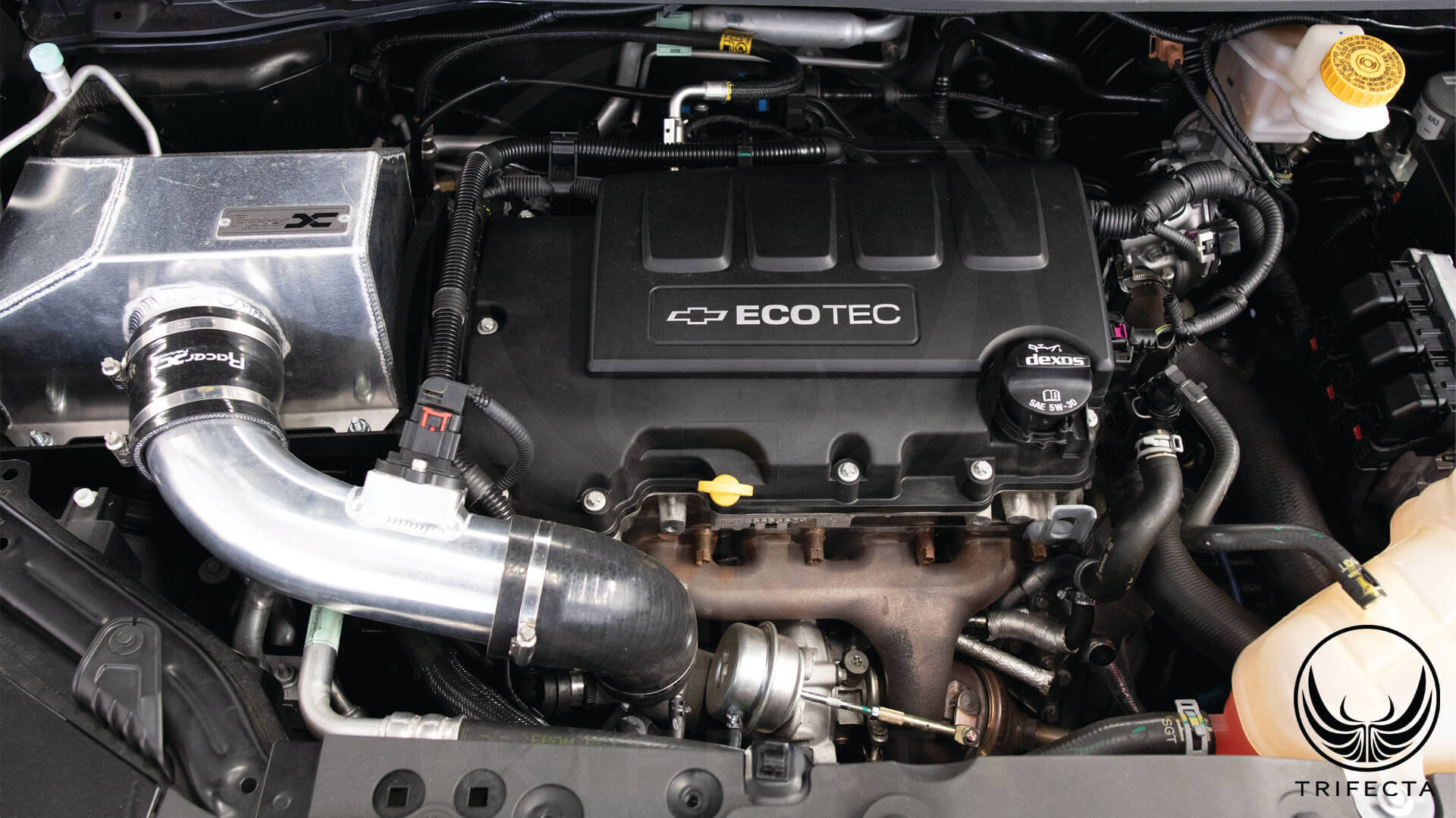
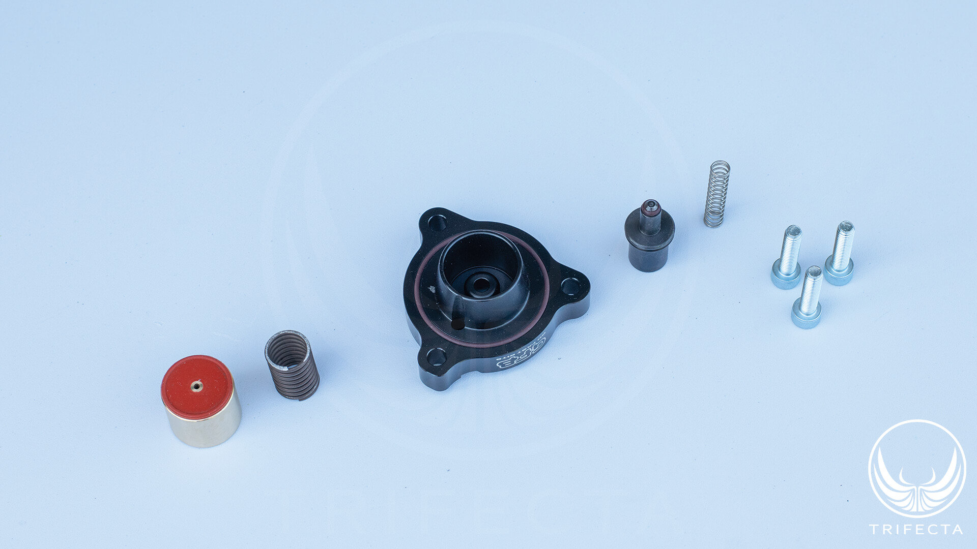 Introduction: Turbocharger Bypass (or blow off) Valves Unless it’s an extreme racing application, gas engines utilizing a turbocharger typically need some way to “blow off” the boost pressure in the event there’s a sudden reduction in power request from the driver. Consider the scenario where an engine that is operating under full boost pressure, the turbocharger is spinning at full speed, and the driver suddenly takes their foot off the accelerator pedal. In order to slow the engine speed down, the throttle blade will close. However, the turbocharger is still spinning at full speed and continuing to compress air. Eventually, the compressed air behind the compressor will build up so much pressure that it will push back through the compressor (this is called compressor surge). Compressor surge can destroy a turbocharger in short order, so to avoid this scenario, automakers incorporate a mechanical valve that diverts the compressed air coming out of the compressor outlet back into the compressor inlet. Old School: Pressure-Mechanical bypass valves Bypass valve found on 1.4L Turbo (RPO: LUJ/LUV) Historical bypass valves were pneumatic-mechanical devices. They would use the pressure supplied to the intake manifold while the engine is under boost to push the bypass valve closed, and keep it closed. If the pressure in the manifold drops because of a throttle closure, the pressure from the compressor would push the bypass valve open to avoid compressor surge. On most modern applications, there’s also a bypass control solenoid that allows the ECU in the vehicle to disable the pressure signal even if there’s positive pressure in the manifold. It might do this because of a boost control system failure to ensure the engine is not allowed to develop any boost. One drawback to the legacy system is its complicated and failure-prone. There’s plumbing from the manifold to the control solenoid, and more plumbing to the bypass valve assembly itself. It’s always possible the bypass valve itself could fail, as well. Modern Era: Electronic bypass valves Bypass valve found on 1.4L Turbo (RPO: LE2) The newer turbocharger designs from General Motors aim to reduce system complexity by utilizing an electronic air bypass valve on the turbocharger. Here, a self-contained electromagnetic-mechanical device attached directly to the turbocharger compressor housing can bypass the air by simply receiving a signal from the ECU. One of the two pins is connected directly to a fused +12v source, and the ECU controls the ground pin. The default position (unpowered) results in the valve staying closed (through spring pressure). In order to open the valve, the ECU supplies the ground signal, which energizes the coil and pulls the plunger against the spring to open the valve. GM 2.0T (RPO: LTG) and 1.4T (RPO: LE2) engines use the electronic bypass The 2.0T LTG engine made its debut in the 2013 Cadillac ATS, and 2013 Chevrolet Malibu, and so far as we know, is the first application to use the electronic bypass valve. Later, in 2015, the overseas Chevrolet Cruze arrived with the 1.4T LE2 engine which also uses the same electronic bypass valve. In 2016, the US and other global markets received the 1.4T LE2 engine in the Chevrolet Cruze and certain models of the Buick Encore. 2016 was also the first model year of the Gen6 Chevrolet Camaro that has the LTG as an option. Virtually every known “next generation” GM turbocharged engine design at the time of writing has, or will have an electronic bypass valve, including: 1.2T RPO: LIH 1.35T RPO: L3T 2.0T RPO: LSY 2.7T RPO: L3B 3.0T RPO: LGY 4.2T RPO: LTA Limitations in the OE electronic bypass valve design The OE bypass valve relies on a relatively weak spring to keep the bypass valve closed when it isn’t energized by the ECU. While it may be adequate for OE boost levels, performance enthusiasts that are looking for higher boost or are using a modified turbocharger may run into issues with the bypass valve leaking. The other limitation related to the return spring is that when there’s a transition from an open bypass event to closed bypass event, again, it relies on this spring’s ability to push the valve closed. GFB (GoFastBits) DV+ bypass valve upgrade kit Several aftermarket companies have approached solving the limitations in the OE electronic bypass valve in various ways, but GFB has taken a unique approach. With the DV+, rather than just beefing up the original design, they redesigned the entire valve control system to leverage the compressor boost to open the valve during an open event, and to hold the valve shut when it’s supposed to be closed. In our testing, we have not observed any issue with the OE bypass valve being blown open by excess boost. We compared boost levels on the OE bypass valve versus the DV+ (as well as another aftermarket bypass valve upgrade) and found no differences. This isn’t to say that as the vehicle components age, they won’t develop problems. In fact, we’ve seen a few LE2 engines lately appearing to not hold boost correctly, and we’re looking into whether the bypass valve might be causing the problem. Where these valves can really shine, particularly the DV+, is during bypass open-to-close transitions. Not only does the piston have a stiffer return spring, but the piston travels a shorter distance, and the valve design leverages the compressor boost to get the valve closed more quickly. This results in a noticeable improvement in boost response when going from off pedal to on pedal. Installation of the valve is straightforward. Simply remove the OE valve by disconnecting the battery, disconnecting the electrical connector, and removing the three screws that attach it to the compressor housing. After partial disassembly of the OE valve, the DV+ is assembled on the OE coil assembly and is reattached to the turbocharger with the three new bolts they provide with the kit. Installation took approximately 20 minutes and required no tuning changes. Conclusion The GFB DV+ is a great modification if you’re looking for the best performance you can get out of your 2.0T LTG or 1.4T LE2 engine! It’s a simple, low cost way to improve the vehicle’s boost response. For this application, the part number is T9363 and is available at any of GFB’s distributors. Link: https://gfb.com.au/products/blow-off-and-diverter-valves/dv-plus/t9363/ NOTE: The web site does not list the LE2 as compatible with this product, but we have tested and confirmed it is, on our development vehicles.
 -
TRIFECTA Cruze DIESEL Calibration: +50WHP/+66ft-lbs without DPF issues!
TRIFECTA Performance commented on TRIFECTA Performance's article in News
We provide the ability to flash back to stock for service visits, however we cannot make any claims or guarantees regarding warranty: -
 History of Big Wheels No, we’re not talking about the toy trike you used to have when you were a kid, we’re talking about turbo wheels, and making them BIGGER! When it comes to mods for a turbocharged engine, upgrading the compressor and turbine wheels inside an OE frame turbocharger is an easy way to get decent performance gains without much hassle. Custom “ground-up” designed turbo kits that utilize standard aftermarket turbochargers can yield impressive power, but they tend to be expensive, and in some cases require modifications that are not reversible. For enthusiasts looking for decent gains with a drop-in part need to look no further than a turbo with upgraded wheels! First, it was the Compressor Wheel The first big wheel turbo kits for the 1.4T addressed the compressor wheel size. These turbos utilized a custom machined compressor wheel and compressor housing to increase airflow on the intake (cold) side. Several companies have experimented with different compressor wheels sizes, but in many cases it was hard to justify the cost vs performance gain. Exhaust Flow Challenges On this particular engine, exhaust flow has always been a challenge. The OE turbocharging strategy aims to eliminate turbo lag as much as possible in order to make the vehicles drive as similar to a naturally aspirated engine as possible, which is what most people are used to. This requires a relatively small turbocharger (from a wheel size perspective). Small turbochargers spool very quickly and provide peak boost at a lower RPM, but there’s a trade-off: the cost is having less than spectacular high RPM performance. This is because as engine RPMs rise, so do the exhaust flow requirements, and a turbine wheel size that’s optimized for low to mid RPM operation suddenly becomes a restriction at high RPM. Next, it was the Turbine Wheel Compressor wheels (compared to turbine wheels) are relatively easy to make bigger. In most cases, you take a block of billet aluminum and cut a new compressor out of it. Turbine wheels, on the other hand, are much more challenging (and expensive) to make because they need to be made out of materials that can tolerate the excessive heat of the exhaust stream. The other challenge is whether the OE turbo frame can be bored out enough to accept a larger compressor and turbine wheel. And beyond that, yet another challenge is the core itself. The OE turbocharger on this engine can spin in excess of 250,000 RPM. Installing a larger compressor and turbine wheel adds weight to the rotating assembly, which adds stresses to the shaft and bearings. And now, it’s all about the (exhaust side) A/R “A” what?? A/R. The “internet” defines this separately as “Aspect Ratio”, “Area / Radius” and “Area Ratio”. The short of it is that the A/R describes the ratio of the area of the turbine inlet to the radius of the wheel itself. There’s an A/R characteristic on the compressor side as well. It’s the radius of the compressor wheel compared to the area of the compressor discharge. Modern day big wheel turbo offerings now offer all three upgrades: compressor, turbine and modified A/R to improve exhaust flow characteristics. Supporting the Community As the premier tuner of the 1.4L turbo engine markets, TRIFECTA considers it their duty to provide ongoing calibration support for quality parts that are popular with the community. When the big wheel V2 came out – the first modified OE frame turbo with an upgraded turbine wheel - we jumped all over it. More recently, we were approached with an offer to receive the updated exhaust housing for the V3 turbo, which includes the A/R change. We were excited to have this opportunity! 2016 Chevrolet Sonic 1.4T Manual Transmission Test Vehicle We have several 1.4T equipped vehicles in our test fleet, but for this development process, we chose our 2016 Sonic as the test vehicle mainly because it’s largely stock. We pondered the question: How would a turbocharger like this perform on a vehicle that has few other modifications? Can we make a case for this turbocharger as a “sooner” rather than “later” upgrade? (we plan to add more mods to this vehicle and re-evaluate gains at each mod) Vehicle Specs: 2016 Chevrolet Sonic LT 1.4L turbo (RPO: LUV) engine Manual transmission TRIFECTA ECM and FPCM calibration 60lb Siemens-Deka fuel injectors RacerX cold air intake system Spec upgraded clutch WaveTrac limited slip differential ~22000 miles on the vehicle Installation Notes Well, there’s not much to note! This turbocharger is a drop-in replacement for the OE turbocharger. It took a DIY mechanic about 4 hours to do. The turbocharger replacement procedure calls for new gaskets and seals, but given the relatively young age of this car, we reused all of the gaskets and seals without issue. The only item we needed was some coolant to replace the coolant lost when disconnecting the turbocharger’s coolant lines from the block. Dyno Test Notes After installing the turbocharger, we took the car over to our local dyno. All pulls were done in 3rd gear, and were performed on a Dynojet 424xLC2 chassic dynamometer (with the load cells disabled). For turbocharged applications, we provide results as UNCORRECTED. Below are some highlights from the dyno sheet: Vehicle Config Max HP Max TQ HP Gained vs stock TQ Gained vs stock Stock turbo / cal 132 156 – – V3 / cal – 2000 RPM 44.6 117.2 - 5.1HP - 13.39TQ V3 / cal – 2750 RPM 78.8 150.5 - 0.87HP - 1.65TQ V3 / cal – 3000 RPM 95.2 166.7 + 8.18HP + 14.29TQ V3 / cal – 3750 RPM 170.6 239.1 + 66.54HP + 93.27TQ V3 / cal – 3892 RPM* 182.5 246.3 + 75.47HP + 101.85TQ V3 / cal – 4183 RPM** 193.0 242.3 + 82.4HP + 103.1TQ V3 / cal – 4891 RPM* 203.5 218.6 + 79.01HP + 84.9TQ V3 / cal – 6000 RPM 190.2 166.2 + 64.4HP + 56.28TQ * - PEAK HP and TQ RPM samples ** - Maximum gain vs stock (HP AND TQ) Additional Notes: Stock turbo / cal configuration includes upgraded clutch and Wavetrac LSD All V3 samples include TRIFECTA calibration V3 is ZZP Big Wheel V3 turbocharger Discussion of Test Results In general, we were quite impressed with the results. This particular dyno is notoriously “stingy” and we managed to break 200WHP and hit almost 250WTQ. We noted a slight drop in power below 3000 RPM (likely due to the increased exhaust flow required to spool the turbo), but by around 2750RPM, the power levels were almost the same. The power curve is surprisingly flat. We expected to see the power take a nose-dive at higher RPM, but with proper calibration we were able to get the power to hold decently - past 6000 RPM. We have further dyno results that show a smoother curve at higher RPM, but we chose this dyno chart to highlight the gains. For a vehicle that has so few mods, it performs amazingly. We would, however, caution that anybody planning on purchasing this turbocharger also upgrade their clutch – slippage on the stock clutch at these power levels is almost certain. We also noted that we could not achieve a manifold pressure much beyond 280kPa. The pre-throttle body pressure can rise as high as 310kPa, but even with the throttle body wide open, the manifold pressure would not rise beyond 280kPa. We believe either/both of the following are true: 1. Throttle body is causing a pressure restriction, and/or 2. There’s turbulence inside the intake manifold disturbing airflow. If this issue is resolved, we believe the peak torque numbers could rise even higher, though high RPM horsepower numbers aren’t likely to change much. Fuel injector upgrade is a requirement for this turbocharger. At the time of writing we had only evaluated the 60 lb/hr Siemens-Deka fuel injectors, but we suspect 42 lb/hr or larger will be necessary. This vehicle has the OE intercooler and exhaust system (including the OE catalytic converter). We used the wastegate actuator provided with the V2/V3 turbocharger. We plan to retest the vehicle with additional modifications. Calibration Availability The V3 turbocharger is popular this season. A number of our customers have either installed it or are planning on it. At the time of writing, our calibration is still under development but is largely complete (past 90% completion). TRIFECTA customers may contact our support team and request calibration support for the V3 at this time. As always, any future refinements will be available to our customers at no charge.
 -
 To that end, if any of our tech-savvy followers or customers want to help us fight Covid-19, we invite you to join our Folding@Home team! Folding@Home is, in a nutshell, a method of crowd-sourcing CPU cycles to help researchers simulate how new drugs might interact with the virus. The more CPU (and GPU) cycles people can donate, the faster researchers can go through iterations which may accelerate the path to a vaccine! For more info on Folding@Home, visit: https://foldingathome.org/ Our Team Number is 252535! https://stats.foldingathome.org/team/252535
 -
Hi Pete, This is a do-it-yourself modification, and you do not need to remove any modules from the vehicle. All you need is a Windows 7 or greater laptop and our interface cable. You can check out our user guide for a better look at the flashing process: https://www.trifectaperformance.com/ezflash-user-guide.html/
-
 TRIFECTA products are only installed using EZ Flash software With the exception of in-person dyno tuning, all TRIFECTA products are installed using a Windows based application that runs on a Windows PC, or inside a Windows virtual machine (VM). This application is called EZ Flash, and the splash screen will look as follows: In some cases, TRIFECTA has provided “rebadged” versions of EZ Flash to resellers, however, at present, none of those resellers are active. TRIFECTA products are only installed using EZ Flash, and never installed using any other piece of software. TRIFECTA products are only installed using a USB to OBD-II adapter Over the years, TRIFECTA has supported only four different types of USB to OBD-II adapter for installing its products: The “black box” which is a retangular box with a USB connection on one side and a 15pin D-Sub connector on the other side, which the OBD-II cable attaches to. (pre-2010, no longer supported) Special version of the Tactrix OpenPort2 USB to OBD-II adapter. (pre-2010, no longer supported) The “red cable”, which is a special version of the OBDLink SX OBD-II diagnostics tool. It is a one-piece assembly with a USB connector on one end of the cable and an OBD-II connector on the other end. It may carry the TRIFECTA logo, though some units in the field will say OBDLink SX (see below). The “black cable” which, like the “red cable” is a one-piece assembly. It carries the TRIFECTA logo and the model number TFEZ010U (see below). Illustration: TRIFECTA “Black Cable” Illustration: TRIFECTA “Red Cable” TRIFECTA calibrations are never installed using stand-alone handheld devices or any other “flash cable”. TRIFECTA will vigorously investigate alleged instances of sales of “fake” product Individuals or entities that choose to engage in the activity of selling products or services that are advertised as TRIFECTA products or services, and that are mutually understood to be genuine TRIFECTA products or services by both the buyer and seller, but are in fact not genuine TRIFECTA products should be aware that they are likely: Violating various laws regarding fraud and misrepresentation Causing damages to the TRIFECTA brand Displacing profits that TRIFECTA was entitled to Exposing themselves to substantial civil monetary penalties Exposing themselves to criminal penalties TRIFECTA will vigorously defend its brand, will investigate all alleged instances of fraud, and, when appropriate, refer the results of its investigation(s) to authorities if it believes a crime has been committed. Contact us if you have concerns If you are located in North America, and you believe you were sold what was represented as a TRIFECTA product or service and you have a reason to believe it was not an authentic TRIFECTA product or service, please contact us via email at: genuine@trifectaperformance.com
 -
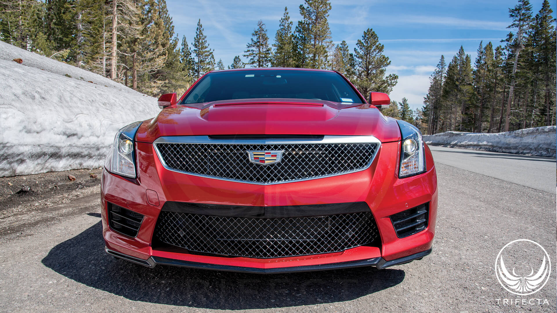 If you are a current TRIFECTA customer, we offer this update to you at no charge! Contact us for details: https://www.trifectaperformance.com/contact Applications: 2014--2019 CTS V-Sport 2016--2019 ATS-V
 -
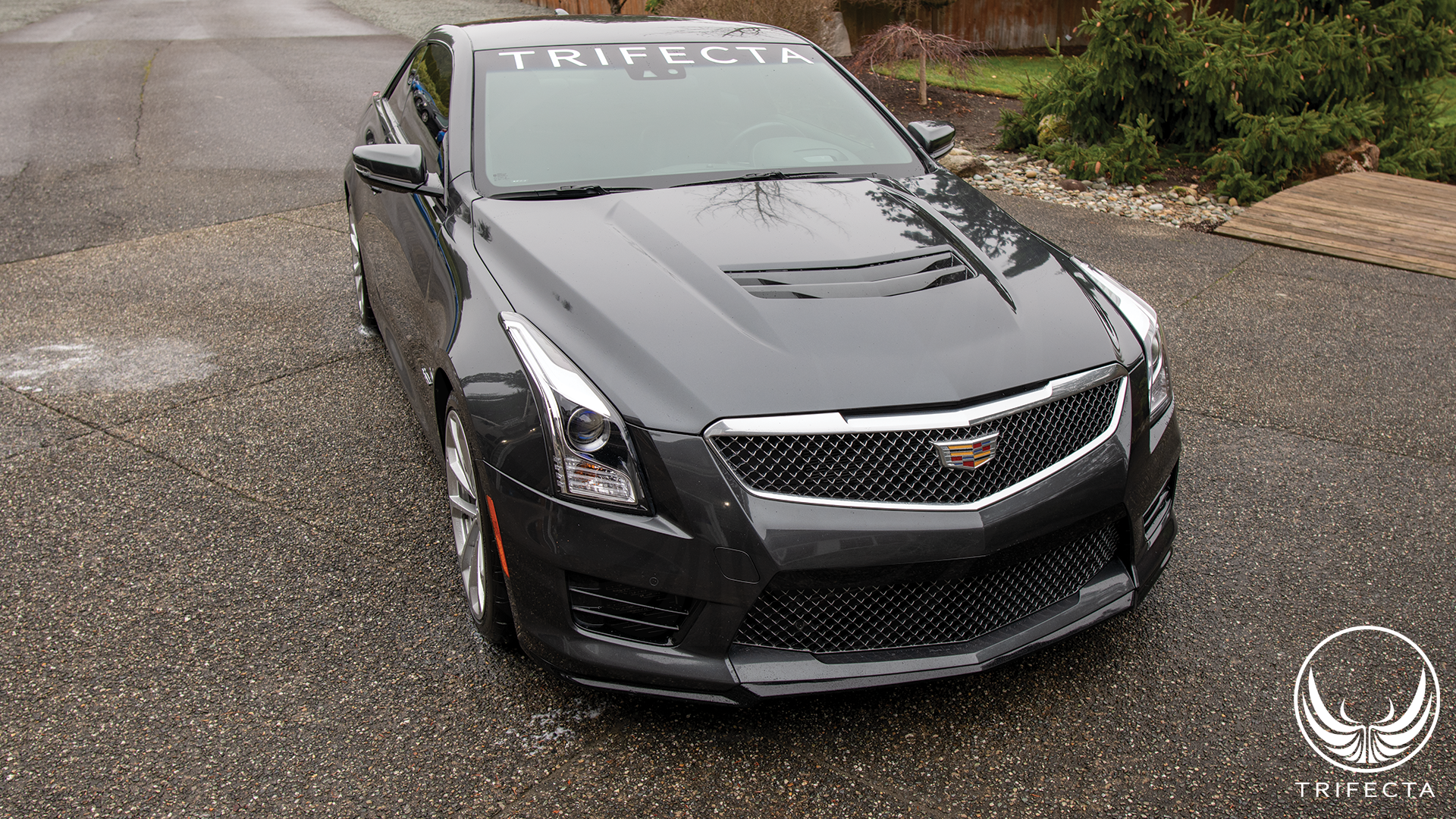 This car is equipped with a Manual transmission, and will join our Automatic transmission ATS-V in development duty, ensuring we are able to faithfully serve owners of both gearboxes as we continue to push the limits of the ATS-V!
 -
TRIFECTA presents: Chevrolet Equinox 2.0L Turbo Performance Calibration
TRIFECTA Performance commented on TRIFECTA Performance's article in News
Hi, Performance is actually not reduced versus stock under 35mph. The dyno is only one way to measure performance, and it can be inaccurate at lower loads depending how throttle was applied after starting the "run". If you check out the Reviews section of our Equinox product page, I think you'll see our Equinox customers all generally agree it is anything but under-powered from low rpm. Yes, you can flash the ECM back to stock at any time. See above for our comments on warranty. -
TRIFECTA presents: Chevrolet Equinox 2.0L Turbo Performance Calibration
TRIFECTA Performance commented on TRIFECTA Performance's article in News
Hi Charles, If warranty is of utmost importance, we would advise simply not modifying the vehicle in any way until after the warranty period is over. We actually wrote an article about this here: Its really a personal decision, and is typically a fairly low risk one, but there is no definitive way of knowing if the dealership has means of discovering the calibration. Our advice is to weigh how much you want the additional performance versus the possible consequences, and follow your gut. It may be helpful to browse through our customer testimonials as well, in case you need a friendly "nudge" from someone other than the manufacturer of the product. https://www.trifectaperformance.com/testimonials/ -
Consistent Boost Levels on the 1.4T LUJ/LUV Engine
TRIFECTA Performance commented on TRIFECTA Performance's article in News
The wastegate calibration comes at no additional charge if you already have a TRIFECTA tune. 👍 -
Consistent Boost Levels on the 1.4T LUJ/LUV Engine
TRIFECTA Performance commented on TRIFECTA Performance's article in News
No change in daily drivability/reliability once properly calibrated. -
Introducing the world's first All Wheel Drive (AWD) Chevrolet Sonic
TRIFECTA Performance commented on TRIFECTA Performance's article in News
Probably not. The Sonic was a perfect candidate for this given it and the Trax are both on the Gamma II chassis. While it wasn't a direct swap, it was no doubt exponentially easier than trying to do this with a Cruze. For the Cruze, we'd need to source a donor vehicle that uses AWD on the Delta II chassis, but unfortunately none exist.

